Sidebar
extensions:teemip-cable-mgmt
Table of Contents

Cable Management
- name:
- Cable Management
- description:
- Documents cable infrastructures and physical connections between devices
- version:
- 1.3.1
- release:
- 2024-10-29
- TeemIp:
- 3.2+
- iTop:
- 3.1.2+
- code:
- teemip-cable-mgmt
- localization:
- English, French, German
- state:
- stable
- keyword:
- cmdb, cable
- dependencies:
- teemip-framework, teemip-config-mgmt-adaptor
- download:
- teemip-cable-mgmt-1.3.1-126.zip
- github:
- teemip-cable-mgmt
- php-max:
- 8.3
This extension brings to TeemIp objects from the cabling world that will allow you to document the physical connections between CIs.
Vocabulary: by “TeemIp solution” or “TeemIP”, it should be understood: TeemIp standalone or the iTop solution on top of which IPAM for iTop has been installed.
Revision History
| Version | Release Date | Status | iTop Min | IPAM for iTop Min | Comments |
|---|---|---|---|---|---|
| 1.4.0 | 2025-xx-yy | WIP | 3.2.0 | 3.2.0 | - A Cable Category may be set on a Patch Panel and on a Network Socket - The creation of Back End Network Cables from a Patch Panel may be limited to a given number - The organization of a Network Socket is the one of its Patch Panel (if set) or its Location otherwise - A Back End Network Cable may be attached to a Breakout Cable - Local and peer device and physical interface attributes have been added to Cross Connects - Cables that make the path of a Cross Connect are displayed in a tab - Sockets that make the Cross Connect are automatically set or reset with a pointer to the Cross Connect they belong to - Once in production, all device and front end cables of a Cross Connect may be created - Cable names can be automatically computed from a method that may be overloaded - Replace legacy CRUD methods by new CRUD events |
| 1.3.1 | 2024-10-29 | Supported | 3.1.2 | 3.2.0 | - Issue #6 - Can't create second direct cable connection between two devices - Breakout Cable: edit the n:n relations with PatchPanels while on display and not on edition anymore - Breakout Vable: improve automation functions |
| 1.3.0 | 2024-06-26 | Obsolete | 3.1.1 | 3.1.4 | - A Patch Panel can be mounted in an enclosure - Network Sockets can be automatically created for a given Patch Panel - Back End Cables can be automatically created between the sockets of 2 Patch Panels - Number of free & ready Network Sockets in Patch Panels are displayed - Cross Connects and Breakout Cables are now modelized - Wiring paths can be proposed to connect the 2 Patch Panels of a Cross Connect - Documents can be attached to Network Cables |
| 1.2.0 | 2023-12-07 | Obsolete | 3.1.1 | 3.1.4 | - A new Direct Cable class enables the connection between 2 physical interfaces together - The direct connection of 2 CIs is visible in the wiring diagram - Audit rules have been enhanced - Data samples have been added - Objects brought by the extension have their summary card - Add Chinese (simplified) translation |
| 1.1.0 | 2023-07-24 | Obsolete | 3.1.0 | 3.1.0 | - Interfaces with no connections have been removed from the wiring diagram - Network cable class has been split into Backend, Frontend and Device network cable classes - An audit rule identifies the cables connected to one end only - Modelization of cables, sockets and interfaces have been enhanced - A socket can be attached to a location or a patch panel - A tab displays the list of patch panels mounted in a rack - Patch panels can be handled by Molkobain DC view extended |
| 1.0.0 | 2022-12-04 | Obsolete | 3.1.0 | 3.1.0 | - Initial revision |
Features
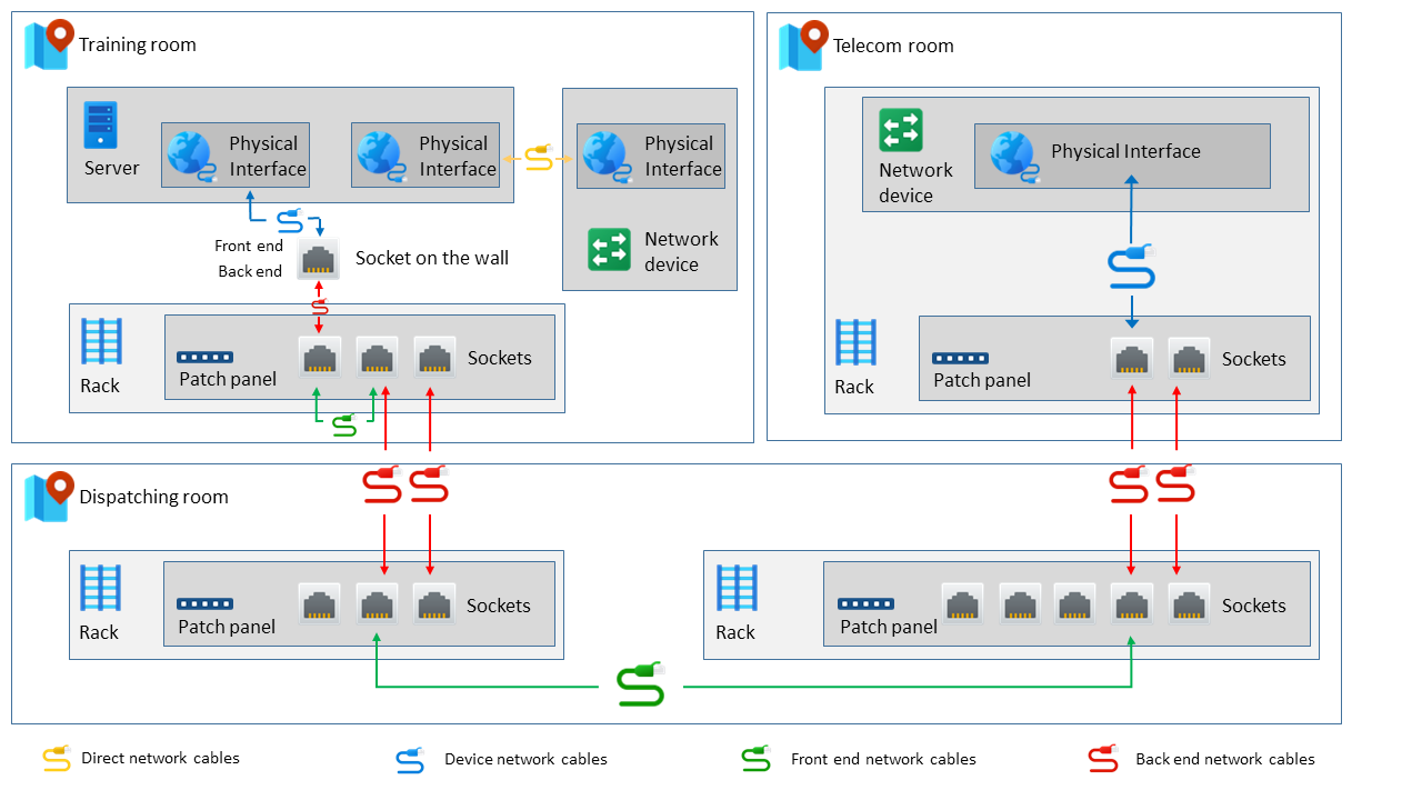
TeemIp cable management allows you to document the cable layouts of your organization. Connect physical interfaces to wall mounted network sockets, to patch panels hosted in racks or to other physical interfaces, document your patch cables and your underlying cabling layout, manage your cross connects: the extension enables a large scope of connection scenarios as the following drawing highlights:
Furthermore, the extension displays the wiring that links devices, physical interfaces and network sockets together, like:
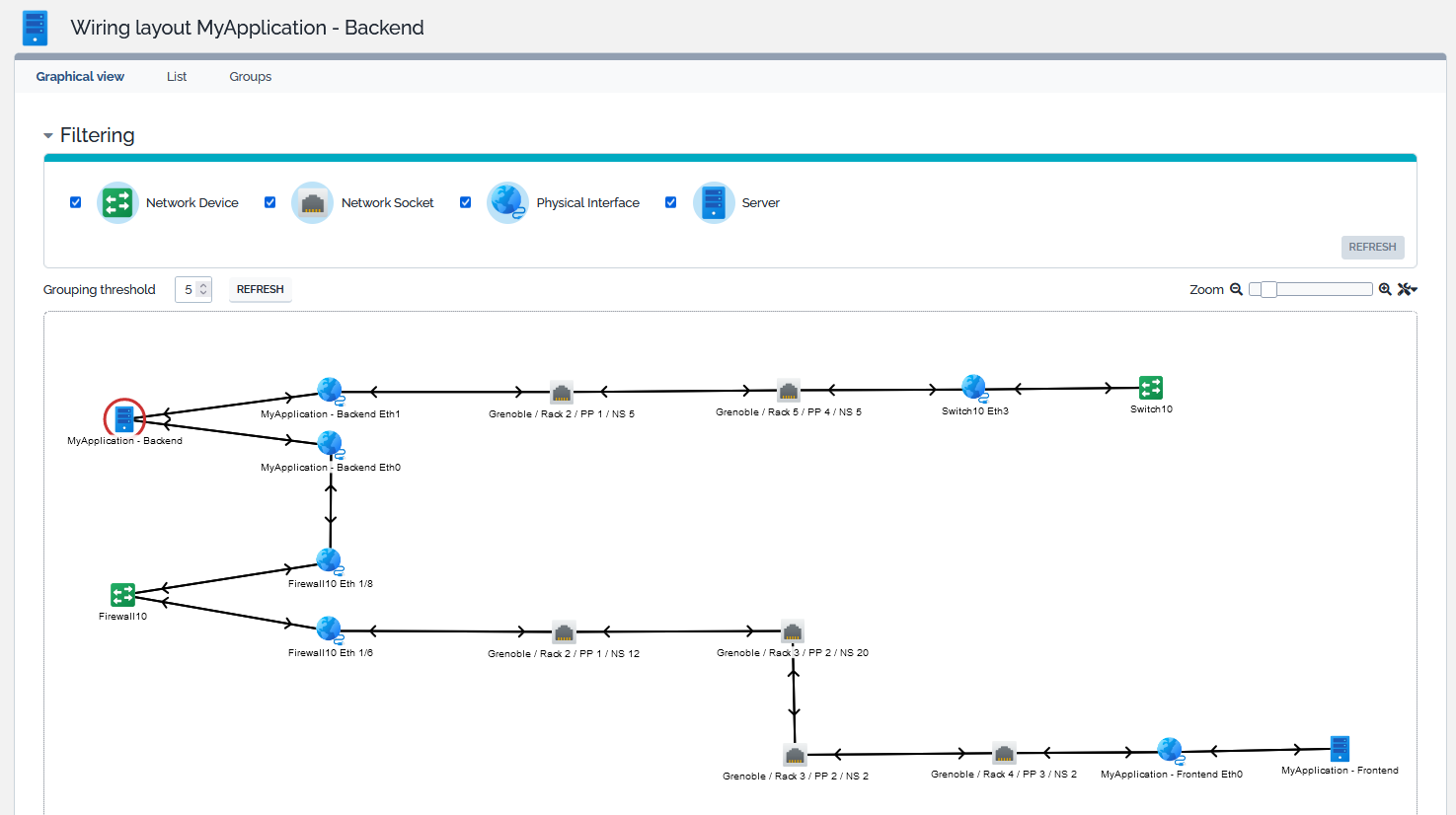
Note that the drawing has been manually rearranged.
Licensing
The TeemIp Cable Management extension is licensed under the terms of the GNU Affero General Public License Version 3 as published by the Free Software Foundation. This gives you legal permission to copy, distribute and/or modify TeemIp Cable Management under certain conditions. Read the ’license.txt’ file in the TeemIp distribution. TeemIp Cable Management is provided AS IS with NO WARRANTY OF ANY KIND, INCLUDING THE WARRANTY OF DESIGN, MERCHANTABILITY, AND FITNESS FOR A PARTICULAR PURPOSE.
Limitations
There is no specific limitations with that extension.
Requirements
TeemIp standalone: The extension is embedded in TeemIp standalone, starting with TeemIp 3.1.
iTop: When installed on an iTop application, you need IPAM for iTop to be installed as well.
In both case, make sure that Datacenter Management has been selected at installation time.
Installation
TeemIp standalone: Installation is done with the application itself, through the setup.
iTop: To add the extension on an iTop application, follow the Standard installation process.
Configuration
No specific configuration is required in TeemIp's configuration file or in IP configs for that extension to work. However, some default settings may be changed:
Configuration file
Under the Modules specific settings section, default parameters used by the Find wiring action on Cross Connects may be overwritten by the following configuration lines.
	'teemip-cable-mgmt' => array (
		'find_wiring_paths' => array (
		  'max_rack_levels_to_cross' => 5,
		  'max_offers_to_display' => 32,
		),
	),
Global IP Settings
Under the Other Settings fieldset, the Allow cabling toward another organizations parameter enables patch panels from a given organization to be connected to patch panels of other organizations.

Implementation Scenario
This section provides, as an example, a method that can be followed to implement TeemIp Cable Management.
- 1. Create the Racks at your different locations.
- 2. Create the Patch panels contained in these different racks.
- 3. On each Patch panel use the Create network sockets menu to automatically create as much network sockets as the Patch panel's capacity.
- 4. Still on each Patch panel, use the Create back end network cables menu to link its Network sockets to remote ones located in another Patch panel that you'll select, and create the associated back end network cables at the same time.
- - Note that such connections and cables may be manually created.
- - Once a back end connection exist for a Network socket, its status will become “Ready”.
- - Back end cables will be listed in the Cables tab of the Patch panel.
- 5. Create your Breakout cables and incorporate the appropriate Back end network cables in them.
- - Breakout cables will be listed as well in the Cables tab of the Patch panel.
Patch Panel

As everyone knows, a patch panel is a piece of hardware with multiple ports that helps organize a group of cables. Each of these ports contains a wire that goes to a different location and can be set for fiber optic cables, cat5 cables, RJ45 cables, and many others. That class allows you to register them in TeemIp's CMDB.
Patch Panel Properties
| Name | Type | Mandatory? |
|---|---|---|
| General Information | ||
| Name | Alphanumeric string | Yes |
| Organization | Foreign key to a(n) Organization | Yes |
| Status | Possible values: Implementation, Production | Automatically computed |
| Location | Foreign key to a(n) Location | Yes |
| External reference | Alphanumeric string | No |
| Description | Multiline character string | No |
| Connectivity | ||
| Capacity | Number of network sockets that the panel can host | No |
| Free sockets | Number of network sockets still available on the panel | Automatically computed |
| Ready sockets | Number of network sockets with status 'ready' | Automatically computed |
| Connector | Foreign key to a(n) Interface Connector Brought by the Network Management Extended extension | No |
| Cable type | Foreign key to a(n) Cable Type | No |
| Cable category | Foreign key to a(n) Cable Category | No |
| Rack Information | ||
| Rack | Foreign key to a(n) Rack | Yes |
| Enclosure | Foreign key to a(n) Enclosure | no |
Should the extension Datacenter View Extended be installed on TeemIp, the rack Informations will be completed with the following additional attribute:
| Name | Type | Mandatory? |
|---|---|---|
| Panel | Possible values: Front, Rear | Yes |
| Zero-U | Possible values: Yes, No | Yes |
| Vert. position | Integer | No |
| Height | Integer | No |
| Weight (kg) | Decimal | No |
Tabs
| Tab | Description |
|---|---|
| Network sockets | All the network sockets attached to the patch panel |
| Cables | All cables connected to a network socket hosted by the patch panel |
| Peer front end panels | List of other patch panels connected to the current one through the network socket port of its hosted sockets |
| Peer back end panels | List of other patch panels connected to the current one through the back end network socket port of its hosted sockets |
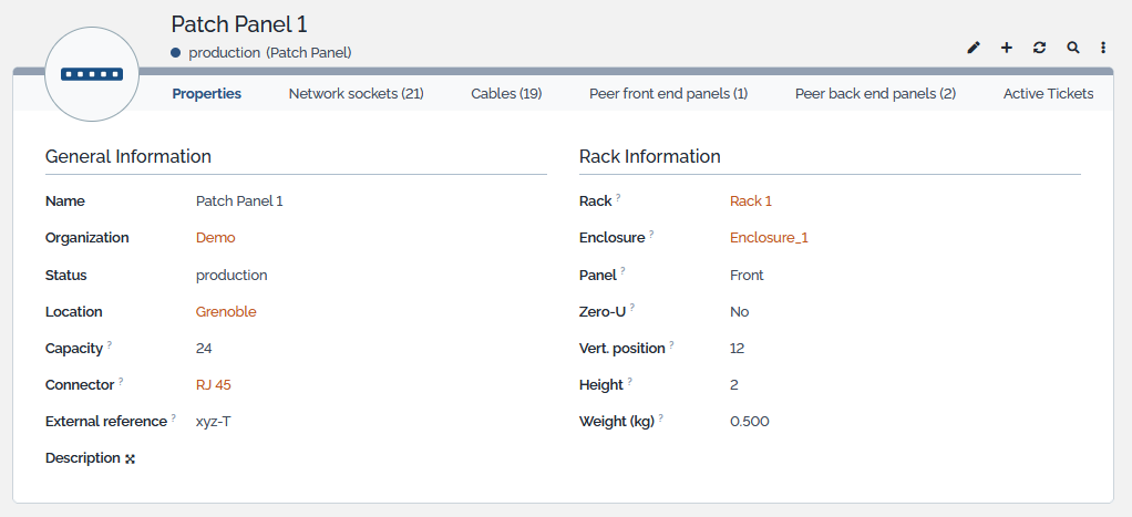
Displaying a Patch Panel
In the Network dashboard that is accessible from a submenu of the standard CMDB overview menu, find the Patch Panel dashlet, click on it and select the item you are interested in:
With the extension Datacenter View Extended, Patch Panel display will look like:
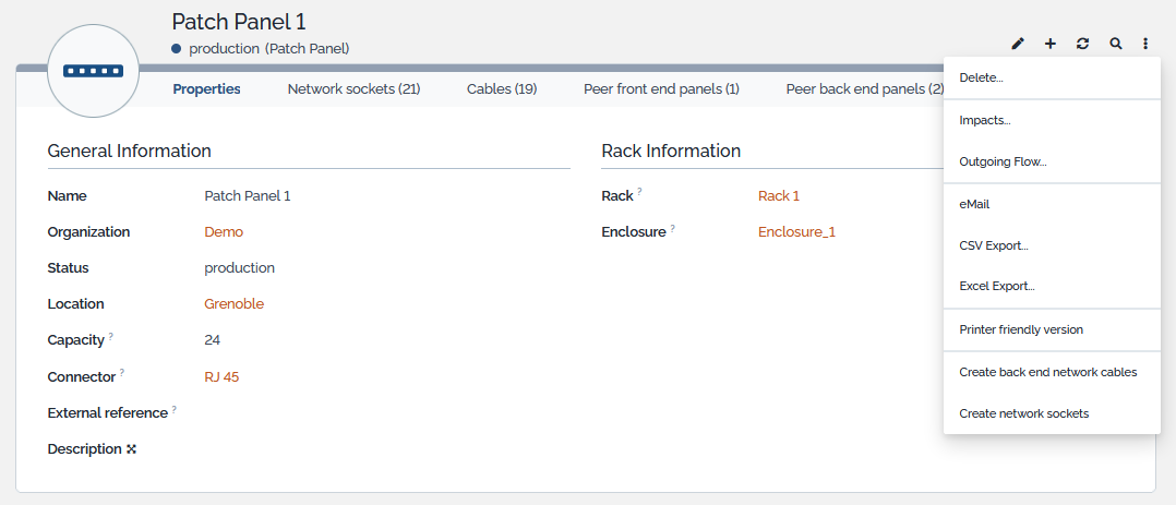
Creating network sockets
If the capacity is set, to value c for instance, TeemIP will offer to automatically create c network sockets and to attach them to the patch panel. If n network sockets do already exist, with n < c, then the menu will still be displayed but only (c - n) network sockets will be created. When created, network socket will be set to inactive mode and will inherit of attributes location, rack, patch panel (obviously) and interface connector (if exists) from the patch panel.
Creating back end network cables
If some network sockets are already attached to the patch panel, TeemIP will offer to automatically connect the back end interface of some of these network sockets to remote sockets located in another patch panel of another Rack. This action removes to TeemIP administrator the burden of creating back end network cables for each of the network sockets attached to a patch panel.
When action is launched, TeemIP offers first to select the number of network sockets to consider and the remote patch panel…
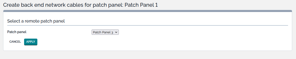
.. before creting the links in accordance with the number of available sockets in the remote rack.
By default, the remote patch panel must belong to the same organization as the source one. This behaviour may be changed through the parameter Allow cabling toward another organization of the Global IP setting of the source organization, as described here.
Network Socket
 A network socket is the passive physical piece of hardware where you plug a network cable to establish a link between different network devices.
Network Socket Properties
| Name | Type | Mandatory? |
|---|---|---|
| General Information | ||
| Code | Alphanumeric string | Yes |
| Status | Possible values: Inactive, Ready, Active | Automatically computed |
| Location | Foreign key to a(n) Location | Yes |
| Rack | Foreign key to a(n) Rack | No |
| Patch panel | Foreign key to a(n) Patch Panel | No |
| Organization | Foreign key to a(n) Organization | Yes |
| External reference | Alphanumeric string | No |
| Comment | Multiline character string | No |
| Front End Information | ||
| Connector | Foreign key to a(n) Interface Connector | No |
| Cable type | Foreign key to a(n) Cable Type | No |
| Cable category | Foreign key to a(n) Cable Category | No |
| Device | Foreign key to a(n) Connectable CI | No |
| Physical interface | Foreign key to a(n) Physical Interface | No |
| Network socket | Foreign key to a(n) Network Socket | No |
| Cross Connect | Foreign key to a(n) Cross Connect | Automatically computed |
| Back End Information | ||
| Back end network socket | Foreign key to a(n) Network Socket | No |
Tabs
| Tab | Description |
|---|---|
| Cables | All cables connected to the network socket |
- The friendly name of a network socket is automatically computed as the concatenation of the location name, rack name (if exists), patch panel name (if exists) and code of the socket.
- The code of the network socket is computed by the method
ComputeCodethat can be overwriten through a datamodel extension. - Its organization is the one of the patch panel, if one has been selected, or the one of the location.
- A network socket can be installed in a patch panel or as a stand alone equipment in a room.
- When installed in a patch panel, attributes Location, Rack and Patch panel are mandatory.
- When standing alone, attribute Location is mandatory but Rack and Patch panel must NOT be set.
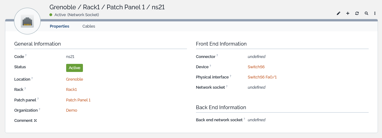
Displaying a Network Socket
In the Network dashboard that is accessible from a submenu of the standard CMDB overview menu, find the Network Socket dashlet, click on it and select the item you are interested in or select it directly from the Patch panel detailed display :
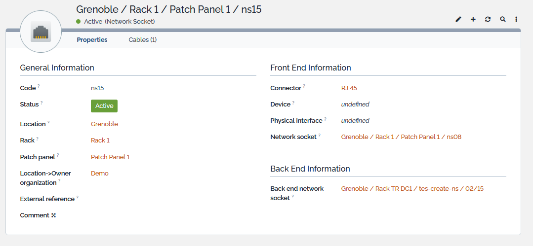
Network Sockets have 2 sides:
- A front end where RJ45 cables or optical fibers are plugged in,
- A back end that links the socket to another network socket.
A few rules are enforced at front and back ends' levels.
- On the front end side,
- A network socket cannot be connected to both a remote network socket and a connectable CI.
- A network socket may belong to a Cross Connect and may be connected to a remote network socket at the same time.
- The front end network socket and the back end one cannot be the same.
Attribute Status is read only and automatically computed:
- If no back end network socket is set, status is set to Inactive,
- If a back end network socket is set but if no physical interface nor network socket is set, status is set to Ready,
- If a Cross Connect is set and if it is Active, status is set to Active
- If a back end network socket is set and if a physical interface or a network socket is set, status is set to Active.
In other words:
| Front End Information | Back End Information | Status | ||
|---|---|---|---|---|
| Physical interface | Network socket | Cross connect | Back end network socket | |
| * | * | * | unset | Inactive |
| unset | * | set and active | set | Active |
| unset | set | * | set | Active |
| set | unset | unset | set | Active |
| All other cases | set | Ready | ||
Attribute Cross Connect, is set or unset from the Cross Connect objet, at the time where the Network Socket is attached to the Cross Connect, as part of the local or peer unit information. See below
Network sockets implements three 1:1 relations. As the datamodel doesn't provide such attributes by default, these 1:1 relations are automatically computed when objects are created, modified or deleted: when one side of the relation is changed, the other sides (new and old when appropriate) are changed. These relations are:
- 1:1 relation between the physical interface of a CI and the network socket attribute of the interface,
- 1:1 relation between the network socket and a remote network socket,
- 1:1 relation between the network socket and a back end one.
Cross Connect
 A cross connect represents the cabling necessary to establish a direct link between two separate organizations in a data center, thus allowing the establishment of a private network link and eliminating the need to connect them using the internet.
Cross Connect Properties
| Name | Type | Mandatory? |
|---|---|---|
| General Information | ||
| Name | Alphanumeric string | Yes |
| Organization | Foreign key to a(n) Organization | Yes |
| Reference | Alphanumeric string | No |
| Peer Organization | Foreign key to a(n) Organization | Yes |
| Peer Reference | Alphanumeric string | No |
| Status | Possible values: Construction, Production, Cancellation, Obsolete | Yes |
| Cable category & type | Foreign key to a(n) Cable type | No |
| Business criticality | Possible values: low, medium, high | No |
| Move to production date | Date (year-month-day) | No |
| Description | Multiline character string | No |
| Local Unit Information | ||
| Location | Foreign key to a(n) Location of Organization | Yes |
| Rack | Foreign key to a(n) Rack | Yes |
| Patch panel | Foreign key to a(n) Patch Panel | Yes |
| Primary Network socket | Foreign key to a(n) Network Socket | No |
| Secondary Network socket | Foreign key to a(n) Network Socket | No |
| Device | Foreign key to a(n) Connectable CI | No |
| Physical interface | Foreign key to a(n) Physical interface | No |
| Peer Unit Information | ||
| Peer location | Foreign key to a(n) Location of Peer Organization | Yes |
| Peer rack | Foreign key to a(n) Rack | Yes |
| Peer patch panel | Foreign key to a(n) Patch Panel | Yes |
| Peer primary Network socket | Foreign key to a(n) Network Socket | No |
| Peer secondary Network socket | Foreign key to a(n) Network Socket | No |
| Peer device | Foreign key to a(n) Connectable CI | No |
| Peer physical interface | Foreign key to a(n) Physical interface | No |
Tabs
| Tab | Description |
|---|---|
| Contacts | All the contacts for the Cross Connect |
| Documents | All the documents linked to the Cross Connect |
| Active tickets | All the non closed tickets related to the Cross Connect |
| Wiring | Wiring diagram |
| Cables | All the cables that make the Cross Connect |
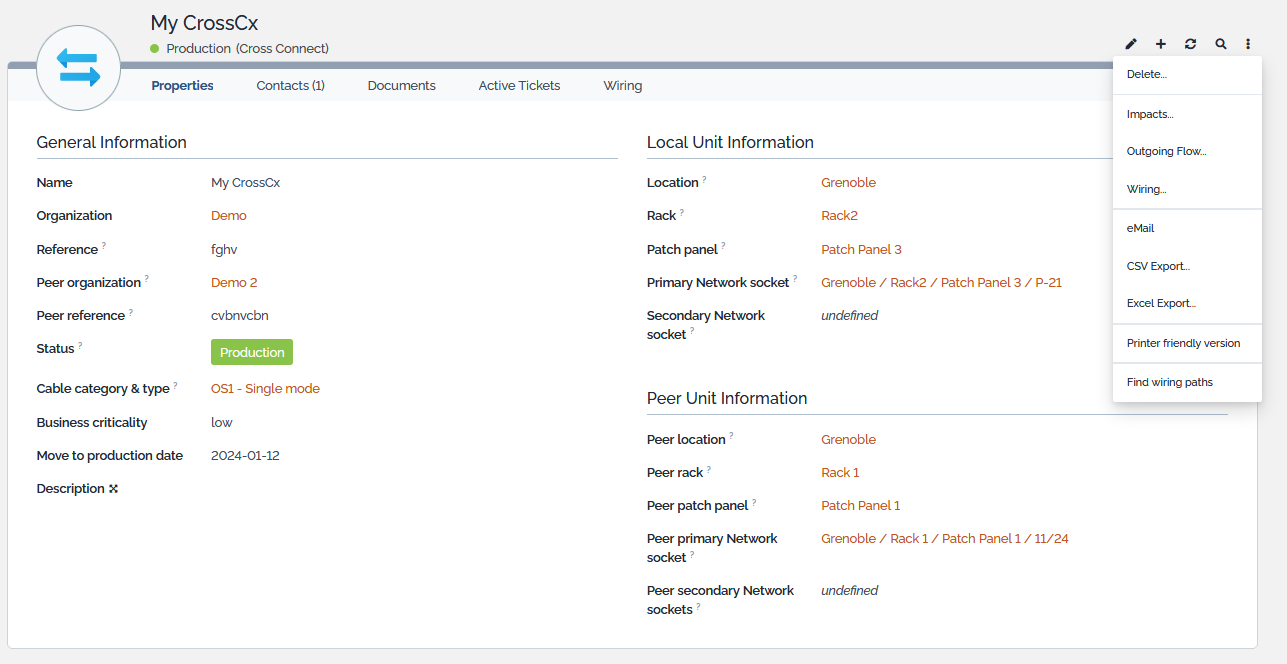
Displaying a Cross Connect
In the Network dashboard that is accessible from a submenu of the standard CMDB overview menu, find the Cross Connect dashlet, click on it and select the item you are interested in :
- When the Cross Connect moves to production state:
- The cables that make the path between the local and peer end are listed in the Cables tab.
- All the network sockets along the path are set with a pointer to the cross connect
- When the Cross Connect exits the production state:
- The Cables tab is not displayed anymore.
- The pointer to the cross connect is reset on all the network sockets along the path
Create Cables
Once the status of the Cross Connect is set to Production, an action available from the Other Actions menu offers to automatically create all the Device and Front End Cables that make the Cross Connect path. However, should it be required, the deletion of these cables remains a manual operation.
Finding Wiring Paths
A cross connect documents a link between one or two network socket hosted in a patch panel sitting in a rack of a given organization and one or two peer network socket hosted in a peer patch panel sitting in a peer rak of a peer organization. The Find wiring paths action will display all the available cabling paths that may be establish to connect 2 network sockets that answer to the previous conditions.
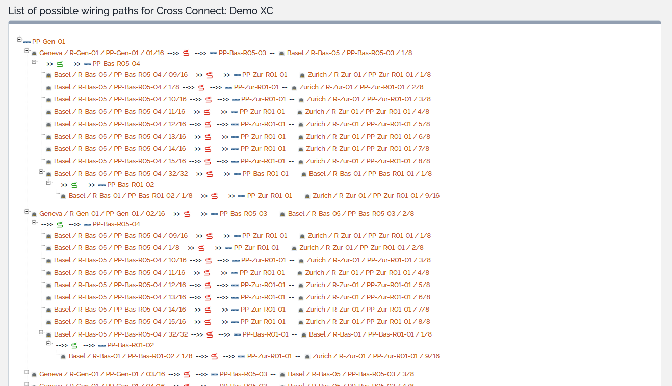
Network admin may select one of the offered path and manually create it within TeemIP.
The Find wiring paths action doesn't scan the entire CMDB. By default:
- The number of racks that the paths may cross is limited to 5,
- The maximum of offers or proposals made by the tool is set to 32.
These value can be overwritten through the configuration file, as described here.
Physical Interface
 TeemIp Cable management extension alters Physical interfaces with new attributes that allow connections to a network socket or to the interface of another connectable CI.
Physical Interface Properties
| Name | Type | Mandatory? |
|---|---|---|
| Wiring Information | ||
| Network socket | Foreign key to a(n) Network socket | No |
| Remote device | Foreign key to a(n) ConnectableCI | No |
| Remote physical interface | Foreign key to a(n) PhysicalInterface | No |
A physical interface cannot be connected to both a network socket and another physical interface.
These 2 relations brought by the extension implement 1:1 relations. As the datamodel doesn't provide such attributes by default, these 1:1 relations are automatically computed when objects are created, modified or deleted: when one side of the relation is changed, the other sides (new and old when appropriate) are changed. These relations are:
- 1:1 relation between the physical interface and the network socket attribute of the interface,
- 1:1 relation between the physical interface and another physical interface.
A connection between a physical interface and a network socket will look as follows.
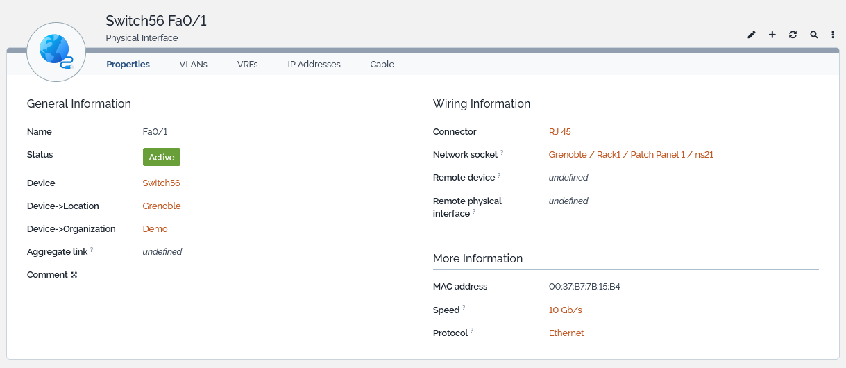
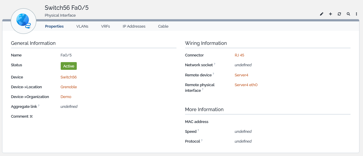
A connection between two physical interfaces will look as follows.
Front End Network Cable
 A front end network cable (known as well as patch cable, patch cord or patch lead) represents the piece of hardware that connects 2 network sockets through their front end.
Front End Network Cable Properties
| Name | Type | Mandatory? |
|---|---|---|
| General Information | ||
| Cable type | Foreign key to a(n) Cable Type | No |
| Cable category | Foreign key to a(n) Cable Category | No |
| Length (m) | Length of the cable, in meter | No |
| Label | Alphanumeric string | No |
| Comment | Multiline character string | No |
| Connecting Points | ||
| Network socket #1 - Front end | Foreign key to a(n) Network Socket | Yes |
| Network socket #2 - Front end | Foreign key to a(n) Network Socket | Yes |
Tabs
| Tab | Description |
|---|---|
| Documents | All documents linked to the front end network cable |
- The friendly name of a front end network cable is automatically computed as the concatenation of the two network sockets' name.
- Its label may be automatically computed through the method SetLabel that can be overloaded.
A few rules are enforced when creating or modifying front end network cables.
- A cable must be connected to 2 different network sockets,
- A cable connecting 2 sockets is unique, regardless the socket used (#1 or #2),
- A cable is automatically updated when one of the sockets it connects is changing.
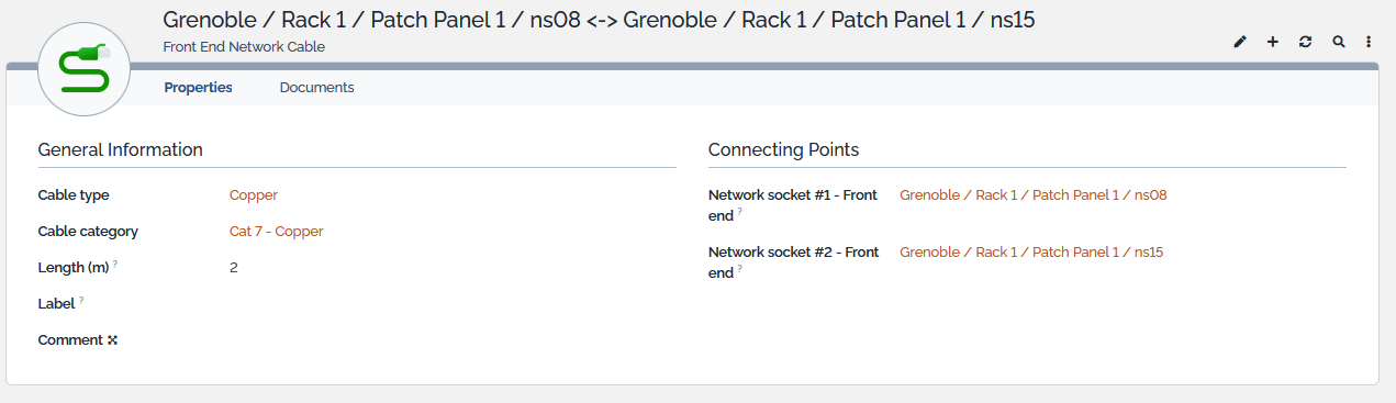
Displaying a Front End Network Cable
In the Network dashboard that is accessible from a submenu of the standard CMDB overview menu, find the Front End Network Cable dashlet, click on it and select the item you are interested in or select it directly from the Patch Panel or Network Socket detailed displays :
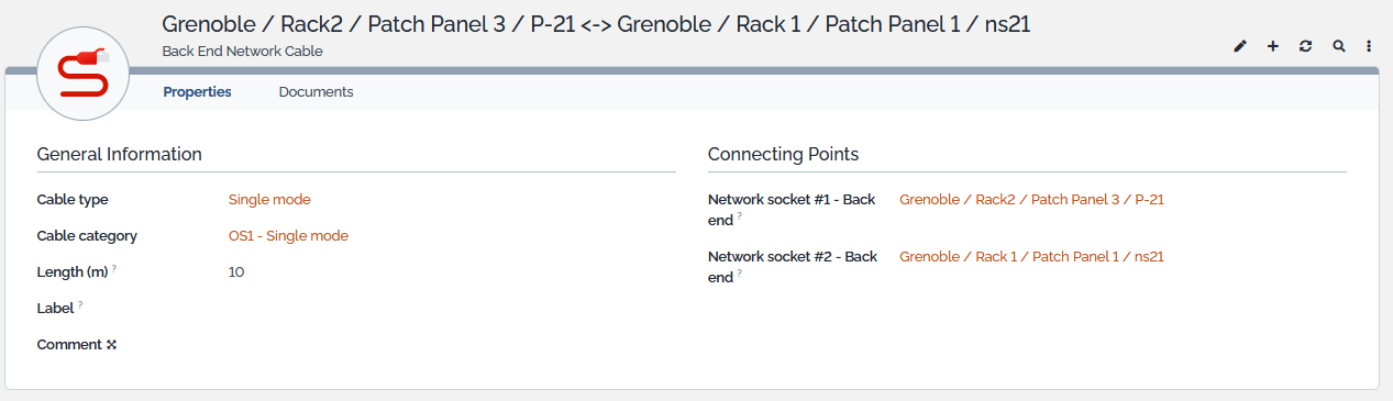
Back End Network Cable
 A back end network cable represents the piece of hardware that connects 2 network sockets through their back end.
Back End Network Cable Properties
| Name | Type | Mandatory? |
|---|---|---|
| General Information | ||
| Cable type | Foreign key to a(n) Cable Type | No |
| Cable category | Foreign key to a(n) Cable Category | No |
| Length (m) | Length of the cable, in meter | No |
| Label | Alphanumeric string | No |
| Comment | Multiline character string | No |
| Connecting Points | ||
| Network socket #1 - Back end | Foreign key to a(n) Network Socket | Yes |
| Network socket #2 - Back end | Foreign key to a(n) Network Socket | Yes |
| Membership | ||
| Breakout cable | Foreign key to a(n)Breakout Cable | No |
Tabs
| Tab | Description |
|---|---|
| Documents | All documents linked to the back end network cable |
- The friendly name of a back end network cable is automatically computed as the concatenation of the two network sockets' name.
- Its label may be automatically computed through the method SetLabel that can be overloaded.
- A back end network cable may belong to a breakout cable
A few rules are enforced when creating or modifying back end network cables.
- A cable must be connected to 2 different network sockets,
- A cable connecting 2 sockets is unique, regardless the socket used (#1 or #2),
- A cable is automatically updated when one of the sockets it connects is changing.
Displaying a Back End Network Cable
In the Network dashboard that is accessible from a submenu of the standard CMDB overview menu, find the Back End Network Cable dashlet, click on it and select the item you are interested in or select it directly from the Patch Panel or Network Socket detailed displays :
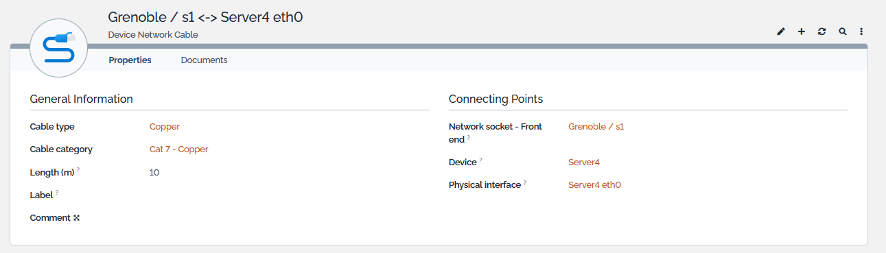
Device Network Cable
 A device network cable represents the piece of hardware that connects the front end of a network socket and the interface of a connectable CI.
Device Network Cable Properties
| Name | Type | Mandatory? |
|---|---|---|
| General Information | ||
| Cable type | Foreign key to a(n) Cable Type | No |
| Cable category | Foreign key to a(n) Cable Category | No |
| Length (m) | Length of the cable, in meter | No |
| Label | Alphanumeric string | No |
| Comment | Multiline character string | No |
| Connecting Points | ||
| Network socket - Front end | Foreign key to a(n) Network Socket | Yes |
| Device | Foreign key to a(n) ConnectableCI | No |
| Physical interface | Foreign key to a(n) PhysicalInterface | No |
Tabs
| Tab | Description |
|---|---|
| Documents | All documents linked to the device network cable |
- The friendly name of a device network cable is automatically computed as the concatenation of the network socket's name and the interface's name.
- Its label may be automatically computed through the method SetLabel that can be overloaded.
A few rules are enforced when creating or modifying device network cables,
- A cable connecting a socket and a network interface is unique,
- A cable is automatically updated when one of its end is changing.
Displaying a Device Network Cable
In the Network dashboard that is accessible from a submenu of the standard CMDB overview menu, find the Device Network Cable dashlet, click on it and select the item you are interested in or select it directly from the Patch Panel or Network Socket detailed displays :
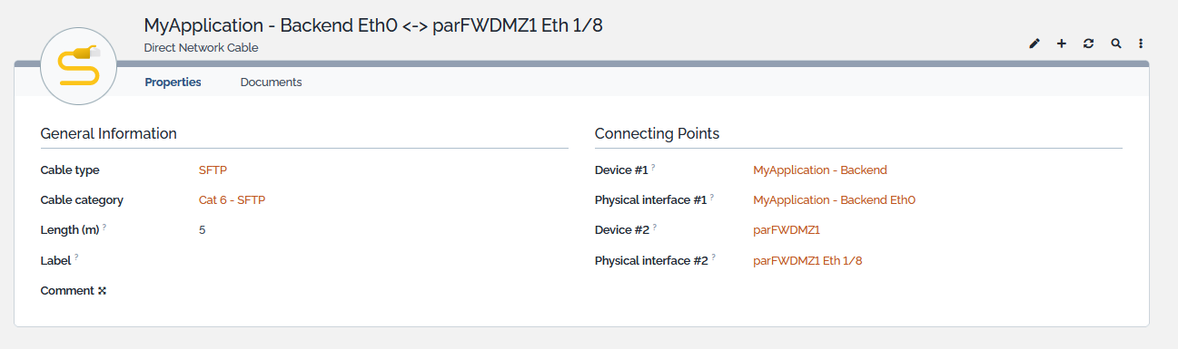
Direct Network Cable
 A direct network cable represents the piece of hardware that connects directly the interface of a connectable CI to the interface of another connectable CI.
Device Network Cable Properties
| Name | Type | Mandatory? |
|---|---|---|
| General Information | ||
| Cable type | Foreign key to a(n) Cable Type | No |
| Cable category | Foreign key to a(n) Cable Category | No |
| Length (m) | Length of the cable, in meter | No |
| Label | Alphanumeric string | No |
| Comment | Multiline character string | No |
| Connecting Points | ||
| Device #1 | Foreign key to a(n) ConnectableCI | Yes |
| Physical interface #1 | Foreign key to a(n) PhysicalInterface | Yes |
| Device #2 | Foreign key to a(n) ConnectableCI | Yes |
| Physical interface #2 | Foreign key to a(n) PhysicalInterface | Yes |
Tabs
| Tab | Description |
|---|---|
| Documents | All documents linked to the direct network cable |
- The friendly name of a device network cable is automatically computed as the concatenation of the two interface's name.
- Its label may be automatically computed through the method SetLabel that can be overloaded.
A few rules are enforced when creating or modifying device network cables,
- A cable connecting two network interfaces is unique,
- A cable is automatically updated when one of its end is changing.
Displaying a Direct Network Cable
In the Network dashboard that is accessible from a submenu of the standard CMDB overview menu, find the Direct Network Cable dashlet, click on it and select the item you are interested in or select it directly from the interace's display :
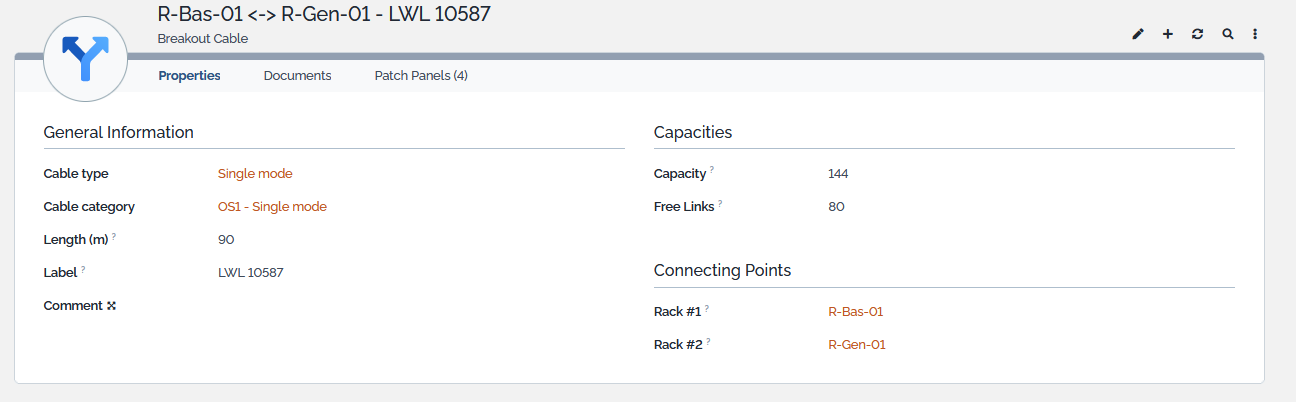
Breakout Cable
 Breakout cables are designed to split or combine optical fibers or copper wires into multiple individual connectors. They eliminate the need for separate cables by consolidating multiple fibers or wires into a single cable bundle which simplifies installation, reduces cable congestion, and improves cable management.
Breakout Cable Properties
| Name | Type | Mandatory? |
|---|---|---|
| General Information | ||
| Cable type | Foreign key to a(n) Cable Type | No |
| Cable category | Foreign key to a(n) Cable Category | No |
| Length (m) | Length of the cable, in meter | No |
| Label | Alphanumeric string | No |
| Comment | Multiline character string | No |
| Capacities | ||
| Capacity | Number of links carried by the cable | No |
| Free Links | Number of links still available in the cable | Automatically computed |
| Connecting Points | ||
| Rack #1 | Foreign key to a(n) Rack | Yes |
| Rack #2 | Foreign key to a(n) Rack | Yes |
Tabs
| Tab | Description |
|---|---|
| Documents | All documents linked to the breakout cable |
| Patch Panels * | All the patch panels that the cable is connected to |
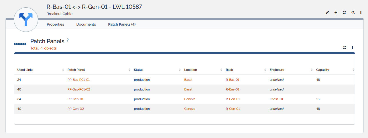
(*) The relation holds a “UsedLinks” attribute which documents the number of wires consummed by the link.
- The friendly name of a breakout cable is automatically computed as the concatenation of the two rack's name and the cable's label.
- Its label may be automatically computed through the method SetLabel that can be overloaded.
- The “Free Links” attribute is read only and automatically computed by the application.
- Value is computed as the capacity minus the maximum of used links with a given rack.
- The breakout cable / patch panel relation holds a “Used Links” parameter telling how many links are consummed by the connection.
- When a relation is created, the “Used Links” attribute is initialized with the value of the patch panel's capacity.
Proper documentation requires that each breakout cable / patch panel relation that concerns a given rack has a counterpart with the other rack.
Displaying a Breakout Cable
In the Network dashboard that is accessible from a submenu of the standard CMDB overview menu, find the Breakout Cable dashlet, click on it and select the item you are interested in or select it directly from the interace's display :
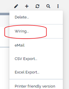
Wiring diagram
Once connections between Devices, Physical interfaces and Network Sockets are documented, the physical path that connects them all can be visualized through the menu “Wiring…” displayed under the “Other Actions” menu of Connectable CIs, Physical Interfaces and Network Sockets.
That action displays the wiring layout that connects the device it has been launch from, and all the elements that are part of the cabling path. For instance, from a backend server application :
- For clarity reasons, only active interfaces are represented on the diagram.
- The layout here above has been rearranged with drag & drops for a better readalibity.
Typology Elements

Two new typological elements are brought by the extension:
| Name | Description | Attributes | Example |
|---|---|---|---|
| Cable Type | Type of a Network Cable | Name, Description, List of Cable Categories using it | Single mode |
| Cable Category | Category of a Network Cable | Name, Cable Type, Description, | OS1, OS2 |
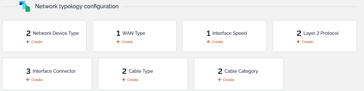
The extension groups network specific typological elements in the dashlet “Network typology configuration”.
extensions/teemip-cable-mgmt.txt · Last modified: by cnaud